CT60 Programmable Clock Generator

CT60 Programmable Clock Generator
There are two solutions for install a programmable clock generator on the CT60 :

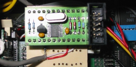
My CTCM prototype...
Because the module need a DIL24 socket and the CT60 clock has a DIL14 socket, you can use some wires for connect the module to the CT60 like this :

ATTENTION !
If you think you're not ready to solder two very fine wires on R11 et R12, return the CT60 and put the 2 wires on the pins 82 and 83 of the SDRAM socket (front right).


|

|
Rodolphe suggest to use the DIL14 socket by the pins 2 (SCL to the pin 83 of the SDRAM socket) and 3 (SDA to the pin 83 of the SDRAM socket) in order to remove easily the clock module.

Mount like me the module on a little board isn't the best solution.
For reduce the wire CLK at the minimum size, the best is to put the top
of the module (pins 18 to 24) on the CT60 clock socket (pins 8 to 14)
with an extension connector. You must at minimum to cut the pins 21/23
on the module, otherwise there are a short circuit with the CT60 CLK and
the 3V3. This solution need to extend the DIL14 socket.
  +------------------------------------------+
  |                                        +5V 3V3   CLK      CLK
  |                                        14o__o__o__o__o__o__o
  |                 +------------------------------------------'8
 +5V   CLK6  CLK5  CLK4  GND   GND           |                 |
  o__o__o__o__o__o__o__o__o__o__o__o_____     )   CT60 clock   |
24| GND   GND   GND   GND   GND   GND    |   |      socket     |
  |                                 |o  o|  1|                 |7
  |                                 |o  o|   o--o--o--o--o--o--o
   )            Module              |o  o|           GND      GND
  |         with a CY27EE16         |o  o|                     |
  |                                 |o  o|                     |
 1| GND   GND   GND   GND   GND   GND    |                     |
  o--o--o--o--o--o--o--o--o--o--o--o-----                      |
+3V3   CLK1  CLK2  CLK3  SCL   SDA +---------------------------+
                         |     |
                         |     |
                         v     v
                        R12   R11 (or pin 82 of the SDRAM socket)
            (or pin 83 of the SDRAM socket)
| CT60 clock (MHz) | CLK5/6 (MHz) | Factor |
| 50.000 | 50.000 | 2/2 |
| 51.000 | 51.000 | 2/2 |
| 51.125 | 34.083 | 2/3 |
| 60.000 | 40.000 | 2/3 |
| 66.625 | 44.416 | 2/3 |
| 75.000 | 50.000 | 2/3 |
| 77.000 | 51.333 | 2/3 |
| 77.125 | 38.562 | 2/4 |
| 80.000 | 40.000 | 2/4 |
| 90.000 | 45.000 | 2/4 |
| 100.000 | 50.000 | 2/4 |
| 110.000 | 55.000 | 2/4 |
The TOS check if the module exist and can change the clock between 50 and 110 MHz.
Look at http://www.ak-modul-bus.de for more informations about this module.
Synoptic :
1 x CY27EE16FZEC.
1 x LM317LZ.
2 x Zener 4V7/500mW.
1 x Quartz 10 MHz.
1 x 180 ohms.
1 x 110 ohms.
2 x 4.7 Kohms.
3 x 100 nF.
1 x male connector HE10 (or HE14) 2x5.

1 x female connector HE10 2x5.
1 x flat cable 10 wires.
1 x female SUBD 9 pins.
Remark : For the frequency to 100 MHz, you must fix the CT60 clock.
|
|
|
ATTENTION !
The CTCM module use the two unused pins on the DIL14 socket by the pins 2 SCL to the pin 83 of the SDRAM socket, and 3 SDA to the pin 83 of the SDRAM socket in order to remove easily the clock module. Solder two very fine wires.

               +-------------+
               |            +5V      CLK      CLK
               |           14o__o__o__o__o__o__o
               |        +-------------'        |8
               |        |    |                 |
               |        |     )   CT60 clock   |
   ____________o__o__o__o_   |      socket     |
  |strap      +5V      OUT  1|SCL SDA          |7
  |  X                  0|   o--o--o--o--o--o--o
  |        CTCM   +-------------+  | GND      GND
  |       module  |      |         |  |
  |               |  +-------------+  |
  +---------------o--o--o-GND         |
                SCL SDA +-------------+
Synoptic

| CT60 clock (MHz) | OUT1 (MHz) | Factor |
| 50.000 | 50.000 | /1 |
| 51.000 | 51.000 | /1 |
| 51.050 | 25.025 | /2 |
| 66.600 | 33.300 | /2 |
| 100.000 | 50.000 | /2 |
| 110.000 | 55.000 | /2 |
Remark : This possibility is disabled on the CTCM module because the CTRL1 pin is at 1 (connected to the +5V).
The TOS check if the module exist and can change the clock between 33 and 66 MHz or 66 and 110 MHz according to the strap on the module.
Look at http://www.powerphenix.com for more informations about this module.
Remark : For the frequency to 100 MHz, you must fix the CT60 clock.
At the left of the 100 MHz oscillator, there are IC3, a CY2309.
Inside this chip there are a PLL (Phase Locked Loop), it's possible to use a part of this chip for obtain a better clock.
The pin 9 is connect to the ground, cut this pin.
  | | | | | | | | |        +------+
 +-----------------+       |      |
 |8               1|       |100MHz|
 |   CY2309       (        |      |
 |9              16|       | OSC  |
 +------------------       |      |
  X | | | | | | | |        +------+

  ^
  |

 here
For do this task, the programmable clock generator module using a CY27EE16 or a DS1085Z-50 must be connected on the CT60's I2C port.
The adjustment works by step of 125 KHz between 50 and 110 MHz for the CY27EE16 (ak-modul-bus module), or by step of 50 KHz between 66 and 110 MHz for the DS1085Z-50 (CTCM module), the value is writed in RAM for a test after 'OK'. The TOS during the boot when the Atari logo arrive send equally this value to the clock, but in case of a problem it's possible to bypass this feature and use the original frequency by press CTRL or ALT.
ATTENTION !
So long as you not cut the power on the machine, the clock gererator works with the latest frequency writed inside his RAM. During the power on sequency, the clock generator copy himself inside his RAM the original frequency saved in his EEPROM. Press on CTRL or ALT has no effect if you not cut the power before.
Initialisation
The original frequency saved in EEPROM is also modifiable after a confirmation with a double click on 'Save' but it's very dangerous !
Yet, when it's impossible to restart the computer, the last solution is to connect the ak-modul-bus module on the MODEM 2 port with a link HE10 SUBD and reprogram in 030 mode the EEPROM of the module with the 'Save' button. This operation is essential for load a new module. The module must be powered by the CT60 and the signals SDA and SCL must be disconnected because during the 030 mode the CT60 force these signals to 0 !

When it's impossible to restart the computer with the CTCM module you must cut the strap for divide by two the frequency (clock between 33 and 66 MHz), and after reprogram again the module with the CT60 by saving a new value inside the EEPROM. Now, the frequency is multiplyed by two when the strap is again in place !
